Mattresses are vacuum-packed for compact transportation, then unpacked and expanded after deployment.
MODULAR ACCOMMODATION SYSTEM / V1
TERRANESTAccommodation that adapts.
A modular, flat-pack accommodation system designed for situations where temporary accommodation needs to last longer.
PANEL1.25 × 1.25 mSTANDARD MODULE
V1 THICKNESS60 mmPRELIMINARY
STANDARD UNIT6 occupantsBASELINE CONFIGURATION
FOOTPRINT3.75 × 6.25 m23.44 m²
DRAG TO ROTATE · SCROLL TO ZOOM
01 / THE GAPWhen temporary
When temporary
becomes long-term.
Emergency shelters prioritize rapid deployment. Permanent construction can require more time, labour, infrastructure and resources. TerraNest is designed to explore the middle ground.
RAPID DEPLOYMENT
TERRANEST
LONG-TERM PERMANENCE02 / THE SYSTEM
Not just a shelter. A system.
One standardized panel becomes a structure that can be built, used, expanded, repaired and relocated.
01BUILD
Flat-pack transport and on-site assembly.
02USE
Safe, functional, dignified living space.
03EXPAND
Add standardized sections when needs change.
04REPAIR
Remove and replace individual panels.
05RELOCATE
Disassemble for another site or use.
↗
MODULAR
Standardized panels form the structure.
↗
FLAT-PACK
Compact stacked transport configuration.
↗
EXPANDABLE
Additional sections can be attached.
↗
REPAIRABLE
Individual panels can be removed and replaced.
1.25 m
1.25 m
TN / PANEL
60 mmPRELIMINARY V1 DESIGN SPECIFICATION
60 mmPRELIMINARY V1 DESIGN SPECIFICATION
03 / THE BUILDING BLOCKOne panel.
One panel.
Many possibilities.
The TerraNest concept is built around a standardized square sandwich panel. The current design uses 1.25 m × 1.25 m panels with a preliminary total thickness of 60 mm.
STATUSProposed material layer. The exact structural performance, bonding method, edge construction and final material specifications remain subject to engineering validation.
04 / CONNECTION LOGIC
Align. Interlock. Secure.
Two panels meet with complementary interlocking teeth and grooves — every tooth on one panel corresponds to a matching groove on the other. The camlock is the mechanical connection; the weather-sealing gasket is a separate sealing mechanism.
01 — ALIGNMENT↓TEETH + GROOVES ALIGN
02 — INTERLOCK↓TEETH ENTER GROOVES
03 — CAMLOCKTwo camlocks per connecting panel edge pull the panels tightly together — proposed mechanical connection
PANELGASKETPANEL
A continuous compressible waterproof rubber gasket is proposed along the mating edge of the panels. When the panels interlock and the camlocks pull them together, the gasket compresses and helps reduce water ingress through the joint.
INTERLOCK → CAMLOCK → GASKET COMPRESSION
Proposed weather-sealing concept — final gasket material, profile, compression and sealing performance require engineering and manufacturing validation. The camlock is the mechanical connector, not the waterproofing system, and the current design is not claimed to be waterproof.1 mm nominal expansion allowance at panel joints — provisional, subject to thermal-movement and joint-sealing validation. This allowance is separate from gasket compression.05 / DESIGNED TO LIVE INEven the essentials
SLEEPING MATTRESSES FOLDABLE STORAGE BOXES
Even the essentials
are designed for deployment.
TerraNest considers not only how the shelter moves, but how essential interior components can be transported efficiently and arranged with dignity in a limited footprint.
FLAT-PACKUNFOLDED ON SITEINTERIOR STORAGE
Foldable storage boxes are transported flat-packed and unfold on site into interior storage compartments.
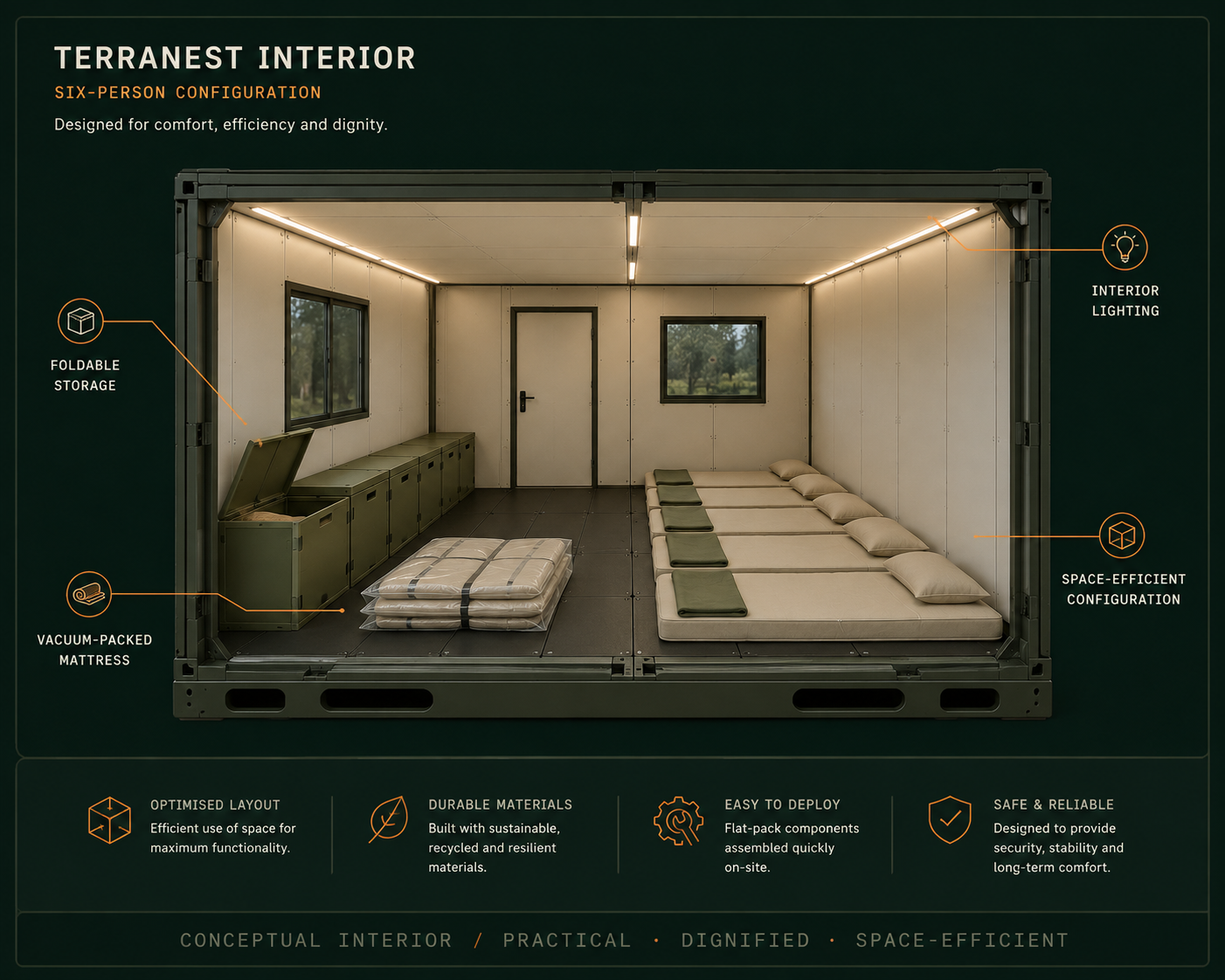 CONCEPTUAL INTERIOR / PRACTICAL · DIGNIFIED · SPACE-EFFICIENT
06 / CONFIGURATION
A baseline, not a limit.
TerraNest expands by adding the same standardized modular panels to the required structural surfaces. The system is not limited to a fixed floor size — additional panels can extend the floor, walls and roof to create a larger configuration. More space, without redesigning the entire structure.
STANDARD / 06 OCCUPANTSSTANDARDIZED MODULAR PANELS · 1.25 M
3.75 m × 6.25 mBASELINE
FLOOR AREA23.44 m²
WALL HEIGHT2.5 m
TOTAL PANELS56
Expansion is a design concept using the same standardized square panels throughout — additional floor area, wall length and roof area. The exact arrangement varies with the required footprint; connection and structural performance require validation. The detailed panel-by-panel layout of the 56-panel configuration is under review.07 / INTEGRATED SYSTEMS
Designed around real conditions.
The Standard Pod provides essential accommodation. Optional energy and water systems can be added for longer-duration configurations.
Essential accommodation.
Elevated steel chassis, floor, standardized wall panels, specialised window panels, door module, roof, sleeping mattresses and foldable storage boxes. 6 occupants · 56 standardized panels. Shelter + sleeping + storage + relocatability — for situations where people may relocate frequently, such as construction worker accommodation between sites.
Standard Pod + infrastructure.
Where people may remain for months or years — refugee accommodation, displaced communities, longer-duration humanitarian settlements — two optional systems can be added to the Standard Pod: solar energy and rainwater harvesting.
Power from the roof.
Solar panels on the roof → electrical connection → interior power and LED lighting. Added where independent energy generation is useful. Wattage, battery capacity and output require validation.
Turning rain into a resource.
Roof → broad roof-edge collection gutter → downpipe → first-flush → filter → foldable water tank beside the pod. Tank form under development. Collected rainwater is not automatically potable.
One system. Different ground conditions.
Ground augers where suitable; ballast blocks where augers cannot be installed. An elevated steel chassis sits between site and pod.
08 / DEPLOYMENT
From flat-pack to living space.
A step-by-step conceptual visualization: the complete deployment kit becomes the six-person TerraNest pod. The current design target is two-person assembly without power tools — a design target requiring validation.
02 / CHASSIS ASSEMBLY
THE FOUNDATION STARTS WITH A FRAME.
The steel chassis is delivered in manageable sections and assembled on site. Depending on ground conditions, it is supported using ground augers or ballast blocks, creating a stable interface between the site and the TerraNest pod.
01 — GROUND PREPARATION
Ground augers where suitable, or ballast blocks where augers cannot be used.
02 — CHASSIS ASSEMBLY
Transportable steel members are connected on site as the chassis takes shape.
03 — POD INTERFACE
The completed elevated steel chassis — ready for the floor and panel system.
GROUND → ANCHORING → STEEL CHASSIS → FLOOR / PANELS
CONCEPTUAL ASSEMBLY VISUALIZATION — SCROLL TO LOAD
01 / FLAT-PACK KIT
The TerraNest deployment kit
Components arrive flat-packed and are assembled on site: chassis, standardized panels, window panels, door module, roof, solar, rainwater hardware, camlocks and interior units.
NOTEPackaging arrangement and transport efficiency require further engineering validation.
STEP 01 / 11
THE TERRANEST DEPLOYMENT KIT
Everything organized for transport, assembly and deployment.
The exact packaging arrangement and transport efficiency require further engineering validation. Window panels and the two-panel door module are specialized configurations within the standard 56-panel system — not additional panels.
- Steel chassis
- Floor panels ×15
- Standard square wall panels
- Roof panels ×15
- Camlocks + connection hardware
- Window panels ×2
- Door module ×1 — two square panels, door pre-fitted
- Solar panels
- Roof-edge collection gutter
- Downpipe
- First-flush diverter
- Filter
- Foldable water tank — transported folded, deployed on site
- Sleeping mattresses
- Foldable storage boxes
OCCUPANTS6
FOOTPRINT3.75 × 6.25 m
FLOOR AREA23.44 m²
TOTAL PANELS56
Standard six-person configuration. Specialized window and door panels are included within the 56-panel count.
RELOCATABLE BY DESIGN
UNLOCK CAMLOCK → SEPARATE PANELS → DISASSEMBLE → RELOCATE → REASSEMBLE
The same connection system works in reverse. The number of reuse cycles requires testing.GROUND CONDITIONS
Choose the approach.
A site-adaptable anchoring system, not one foundation method. The elevated steel chassis remains the interface between the pod and the site. Elevation provides ground clearance, including in areas experiencing heavy rainfall — elevation alone does not make the pod flood-proof.
09 / WHERE IT COULD GO
Accommodation with somewhere to go.
TerraNest is intended for situations where safe accommodation is needed longer than a conventional emergency shelter is designed to provide, but permanent construction is not yet practical.
01
HUMANITARIAN
Refugee and displacement accommodation.
02
DISASTER RESPONSE
Temporary accommodation after disasters.
03
CONSTRUCTION
Long-duration worker accommodation on infrastructure projects.
04
REMOTE PROJECTS
Accommodation where conventional construction is difficult.
10 / TESTING & VALIDATION
Designed to be tested.
TerraNest is an evolving engineering project. The next stage is validation, not assumption.
●CURRENT
○MATERIAL TESTING
○JOINT TESTING
○STRUCTURAL TESTING
○WIND + ENVIRONMENT
○FULL-SCALE PROTOTYPE
○FIELD PILOT
VALIDATION NOTE
8–10 year target service life
Target — requires validation through material, joint, structural, environmental and long-term testing. Final panel weight, solar capacity, water-storage capacity and exact cost are also not yet established.
Panel structural performanceInterlocking joint performanceCamlock performanceWeather-sealing performanceThermal movement + 1 mm allowanceWind loadingImpactFire performanceRepeated assembly / disassemblyEnvironmental exposureExact panel weightManufacturing costSolar capacityWater-storage capacity
11 / TECHNICAL DASHBOARD
The details, honestly labelled.
A concise reference for judges who want to go deeper.
Panel1.25 × 1.25 m standardized panelCURRENT DESIGN
Panel thickness60 mm totalPRELIMINARY
Materials0.6 mm coated-steel outer skin + closed-cell foam core + glass-fibre-reinforced HDPE inner skinPROPOSED
ConnectionInterlocking teeth + grooves + mechanical camlocks — two per connecting edgeCURRENT DESIGN
Weather sealingContinuous compressible gasketPROPOSED CONCEPT — REQUIRES VALIDATION
Expansion allowance1 mm nominal at panel jointsPROVISIONAL
Standard Pod6 occupants / 56 panelsCURRENT CONFIGURATION
AnchoringGround augers / ballast blocksSITE-DEPENDENT
ElevationElevated steel chassisCURRENT DESIGN
EnergyOptional solar system — longer-duration configurationsOPTIONAL / PROPOSED
WaterOptional rainwater harvesting — longer-duration configurationsOPTIONAL / PROPOSED
ExpansionAdditional standardized panels, same modular systemDESIGN CONCEPT
Service life8–10 yearsTARGET — REQUIRES VALIDATION
12 / DEVELOPMENT ROADMAPNot a tent.
Not a tent.
Not a permanent building.
A system.
TerraNest is designed to make temporary accommodation more adaptable, durable and dignified.
BUILT TO ADAPT. DESIGNED TO ENDURE.